Know Where It Is before You Need It
An E07 owner documented access to the 12V battery so other owners and roadside technicians could locate it. This guide arranges the supplied photos in removal order, with separate notes from the Australian owner’s manual.
The battery is towards the rear-left of the front compartment, relative to the vehicle’s direction of travel. Looking in from the front bumper, it appears on your right.
01 · If the Doors Will Not Unlock
Find the Emergency Power Connection
The manual locates the emergency interface behind the front bumper’s tow-hook cover. Its procedure connects the external supply’s positive and negative poles to the corresponding red and black terminals. After the door is opened, disconnect the supply and restore the interface.
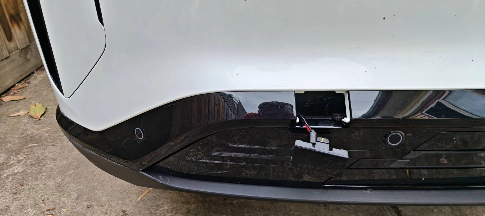
Which Key Unlocks It?
The manual says “key card” in this emergency procedure. It does not clearly confirm whether the supplied Australian key fob works with this connection, or establish that an NFC card is required. The owner report does not resolve this either. Confirm the unlocking method with DEEPAL or roadside assistance.
If the doors already open, this emergency entry step is unnecessary. The manual’s next step is to open the bonnet from inside the vehicle and remove the front storage-box assembly.
E07 Owner’s Manual — pp. 163–165 (PDF pp. 174–176). The removal details below come from a community owner’s experience.
02 · Protect the Rubber Seal
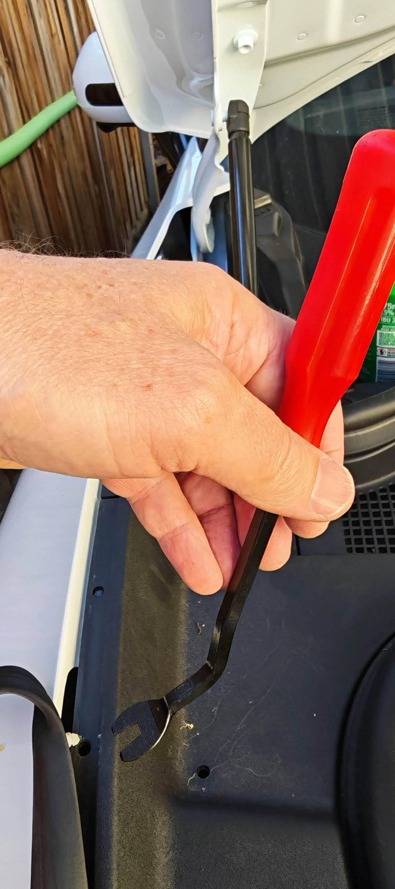
Release the Seal Clips Carefully
The owner report highlights the clips securing the surrounding rubber seal to the body and boot liner. Work carefully at the fasteners rather than pulling on the rubber itself.
03 · Remove the Fasteners
Six T30 Screws and Two Front Scrivets
The owner report identifies six T30 Torx screws in the bottom of the liner and two plastic scrivets at the front of the compartment. The orange markings below show the six screw positions, including the positions beneath the lifted circular covers.
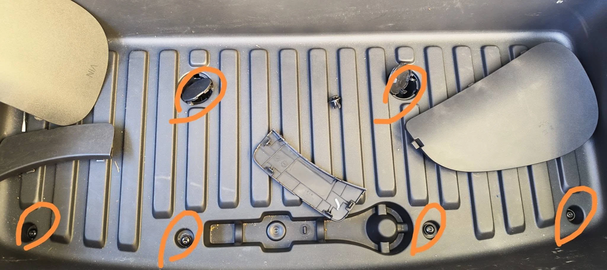
The two front scrivets are described in the owner report but are not clearly identified in these photos. Locate and release them before lifting the liner; do not pull against a fastener that is still attached.
04 · Lift from the Rear Corners
Prise the Liner up Carefully
With the seal clips, screws and front scrivets released, the owner report advises starting at the rear corners, nearest the windscreen. The photo shows a plastic trim tool at the edge of the liner.
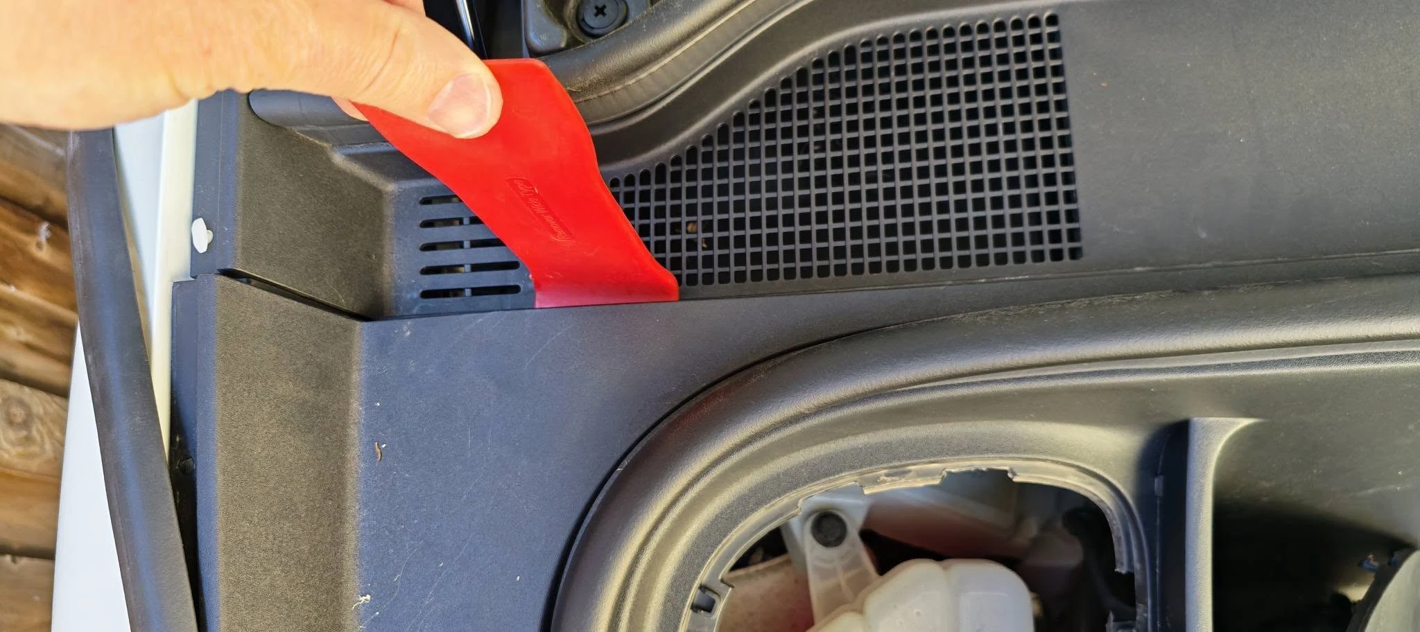
Lift gradually. If a section resists, check for a remaining fastener rather than forcing the liner.
05 · See What Holds It in Place
Twelve Plastic Retaining Clips
This underside view shows the clips around the liner’s perimeter. The owner counted 12 plastic plugs and reported that they came out without breaking.
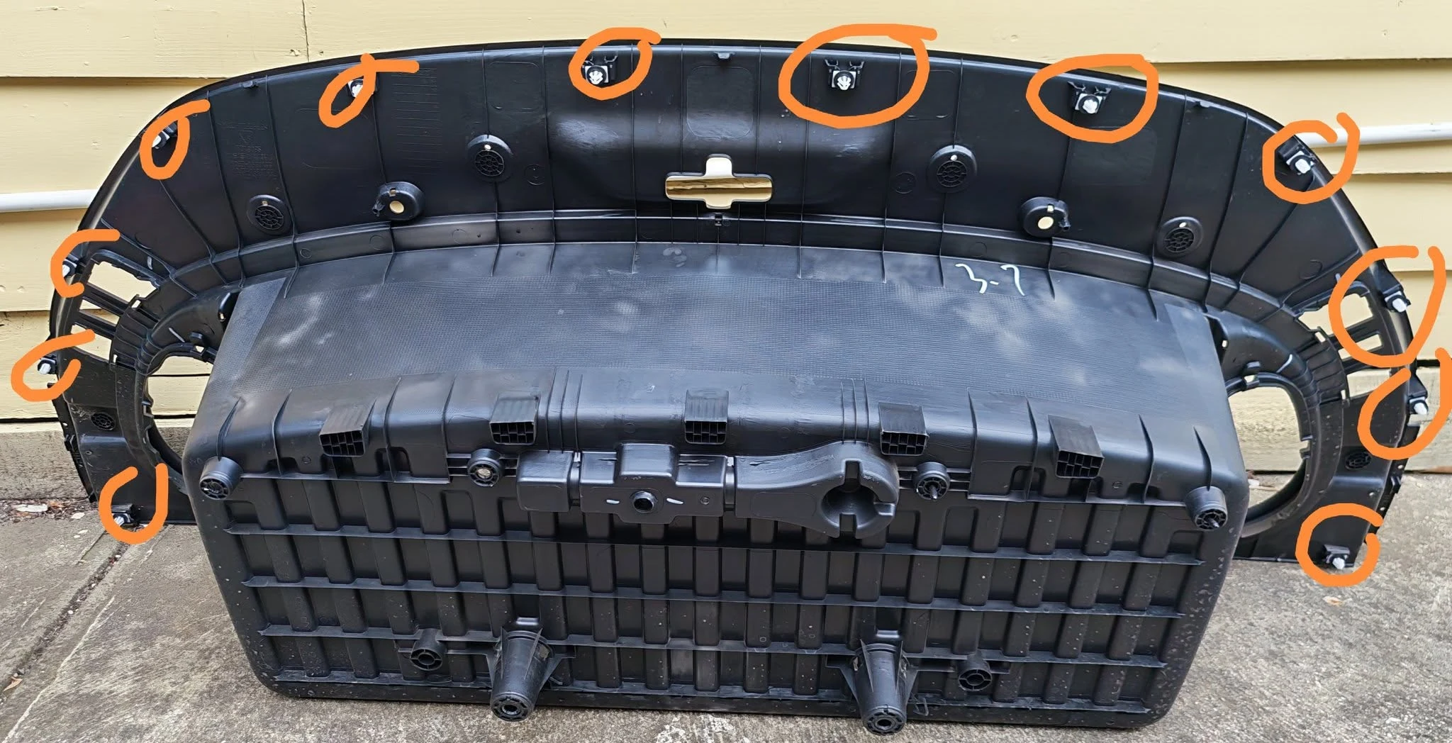
The owner also mentioned greasing the clips for next time. No lubricant type or compatibility was provided, so that is recorded as an owner experience rather than a recommendation for the plastic clips or rubber seal.
06 · With the Liner Removed
Locate the 12V Battery
The battery is at the rear-left of the vehicle’s front compartment—upper right in the photo below, viewed from the front bumper.
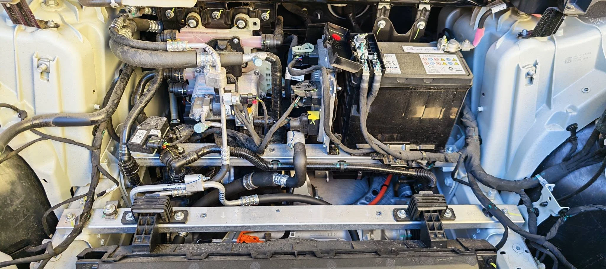
Before Connecting Jump Leads
For the separate jump-start procedure, the manual specifies the vehicle’s positive battery terminal and a battery wiring-harness mounting bolt as the negative connection point. It warns against connecting the jump lead directly to the depleted battery’s negative terminal.
This photo does not identify that designated mounting bolt. Use the manual’s connection diagram and complete sequence (E07 Owner’s Manual — p. 164 (PDF p. 175)), or have roadside assistance perform the work. Never jump-start a frozen battery. After starting, the manual says to disconnect negative first, then positive.
For charging or replacement, have the battery type and suitable procedure confirmed by DEEPAL or a qualified technician. If it repeatedly goes flat, the manual recommends an authorised service-centre inspection.
07 · Identify before Replacing
A Closer Look at the Battery
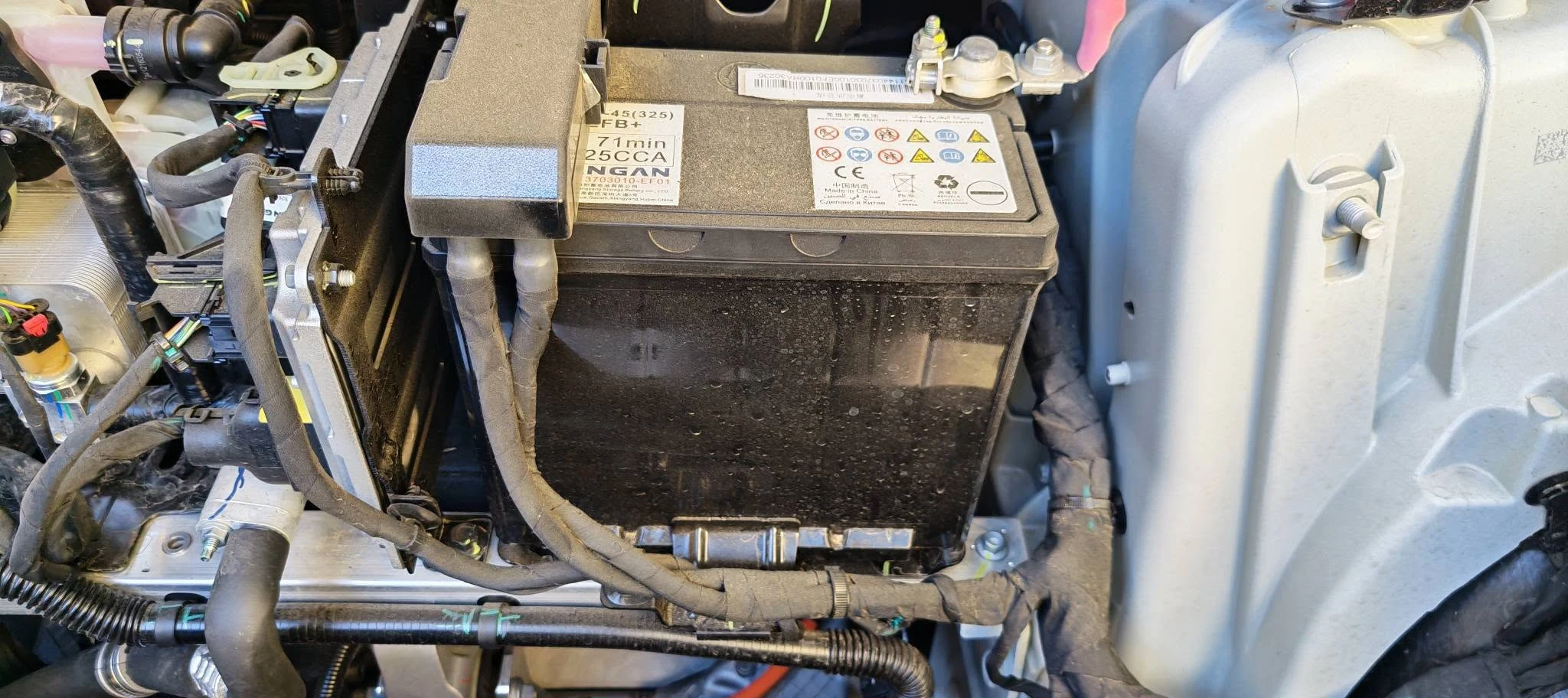
Owner-Suggested Battery Type (Unverified)
“Looks like Yuasa S46B24L, lead acid maintenance free. A little rare but Supercheap sell a Century version.”
Owner observation supplied with the photo
Replacement fitment is unverified. The model suggestion and retailer availability have not been confirmed. Do not order from the suggested code alone: ask DEEPAL or a battery specialist to verify the required battery specification, dimensions, terminal layout and suitability for your E07.
An Additional Owner Photo
An Auxiliary Charge Point?
View the Additional Owner Photo
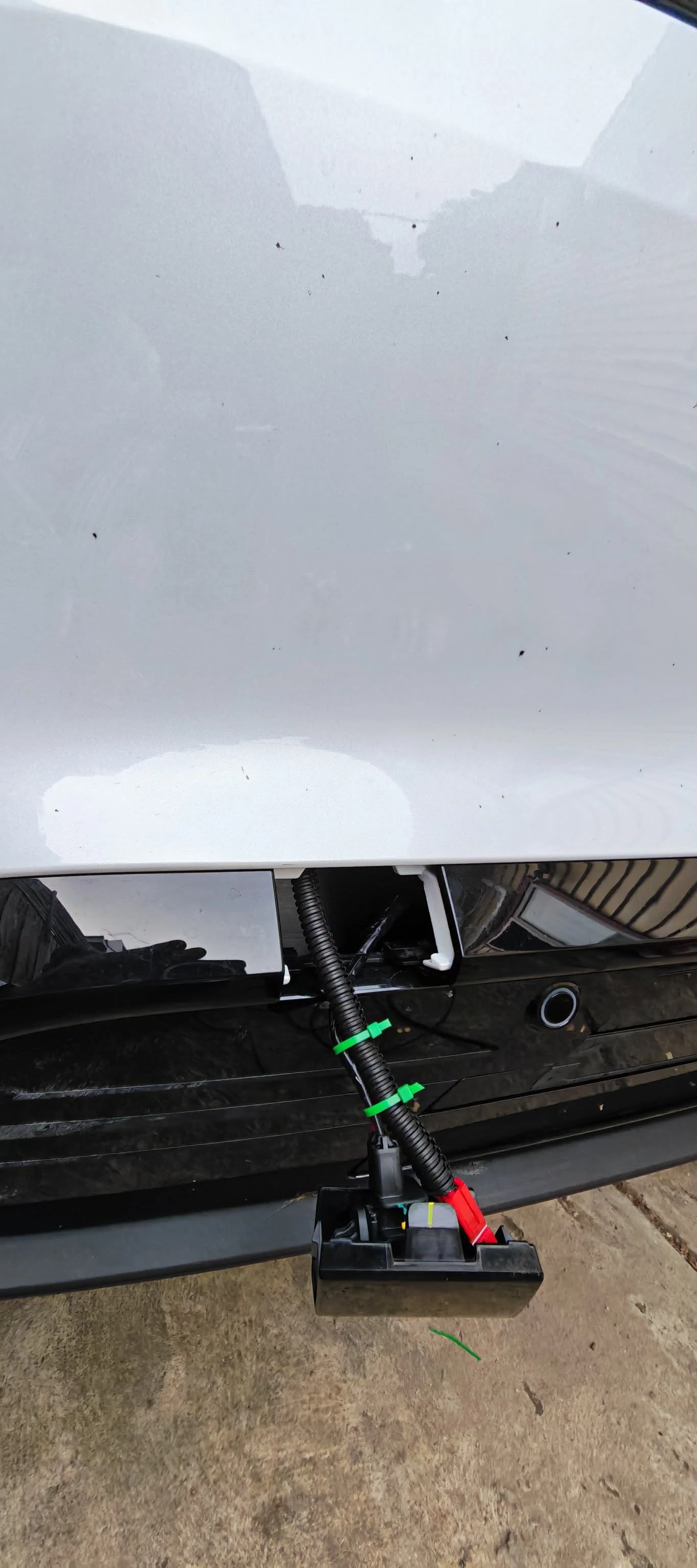
Unverified auxiliary wiring: this photo does not establish a factory charging provision. Do not charge through the emergency entry connector or install an auxiliary lead.
Sources and Notes
This guide uses eight photos and practical notes supplied from a community owner report dated 2 November 2025.
Photo order and explanatory text have been edited for this community guide. Fastener counts and removal tips describe one owner’s vehicle; the official reference is the Australian English E07 owner’s manual revised 22 April 2026.